Rectangular polar moment of inertia, a fundamental concept in engineering and design, plays a crucial role in determining the structural integrity and performance of various components. This guide delves into the definition, applications, calculation methods, design considerations, and comparisons of rectangular polar moment of inertia, providing a comprehensive understanding of this essential concept.
The rectangular polar moment of inertia quantifies the resistance of a rectangular cross-section to bending about an axis perpendicular to its plane. It is a key parameter in analyzing the strength and stability of beams, columns, and other structural elements.
Rectangular Polar Moment of Inertia

The rectangular polar moment of inertia is a geometric property that describes the resistance of a rectangular cross-section to bending about an axis perpendicular to its plane. It is a measure of the cross-section’s ability to resist deformation under applied loads.
Definition and Formula
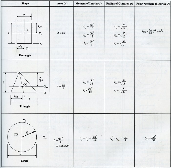
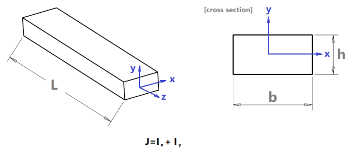
The rectangular polar moment of inertia, denoted by Ip, is defined as the integral of the squared distance from the centroidal axis to the infinitesimal area elements within the cross-section. For a rectangular cross-section with width band height h, the rectangular polar moment of inertia about the centroidal axis parallel to the width is given by:
Ip= (bh 3) / 12
Applications
The rectangular polar moment of inertia is widely used in engineering and design to determine the structural integrity of beams, columns, and other components subjected to bending loads. It is essential for calculating the bending stresses and deflections in these structures, ensuring their safe and efficient operation.
Calculation Methods, Rectangular polar moment of inertia
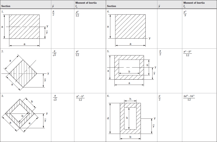
The rectangular polar moment of inertia can be calculated using various methods, including integration and the parallel axis theorem. Integration involves dividing the cross-section into infinitesimal area elements and summing the squared distances from the centroidal axis to each element.
The parallel axis theorem allows the calculation of the moment of inertia about an axis parallel to the centroidal axis by adding the area of the cross-section multiplied by the squared distance between the two axes.
Design Considerations
The rectangular polar moment of inertia is influenced by several factors, including the shape, size, and material properties of the cross-section. A larger cross-section with a higher moment of inertia will have greater resistance to bending. The material’s elastic modulus also affects the moment of inertia, as a higher modulus indicates a stiffer material that resists deformation more effectively.
Comparison to Other Moments of Inertia
The rectangular polar moment of inertia is closely related to other types of moments of inertia, such as the area moment of inertia and the mass moment of inertia. The area moment of inertia is a measure of the cross-section’s resistance to bending about an axis in its own plane, while the mass moment of inertia describes the resistance of a mass distribution to rotational acceleration about an axis.
These concepts are fundamental in understanding the structural behavior of components and systems.
Clarifying Questions
What is the formula for rectangular polar moment of inertia?
The formula for rectangular polar moment of inertia (Ix) about the x-axis is: Ix = (b*h^3)/12, where b is the width and h is the height of the rectangle.
How is rectangular polar moment of inertia used in engineering?
Rectangular polar moment of inertia is used to determine the bending stress and deflection of beams and columns under applied loads.
What factors influence the rectangular polar moment of inertia of a structure?
The shape, size, and material properties of the structure, such as the width, height, and Young’s modulus, influence its rectangular polar moment of inertia.

